
Anchor bolts decide whether the frame fits
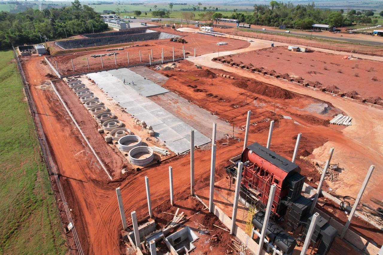
A steel frame leaves the workshop measured to the millimetre. It arrives on site and is landed on bolts that someone else set, in concrete poured weeks earlier, from a different drawing, by a crew who will never see the frame again. That join is where more building envelopes are lost than at any weld in the structure, and it is the one join nobody in the project owns by default.
The frame itself is not usually the problem. Members are cut to programme, holes are drilled from a template, and pre-assembly on the bench proves the parts match each other before they are packed. What pre-assembly cannot prove is whether the bolts on the other side of the world are where the foundation drawing says they are. That gap is closed by paperwork and by one survey, not by steelwork.
The interface nobody owns
On a typical project the foundation is inside the civils scope, the anchor bolts are either inside that scope or supplied loose by the steel fabricator, and the frame is ours. Three parties, one dimension, and no line in any of the three contracts that says whose dimension it is.
Two trades, one dimension
The bolt group belongs on the foundation drawing. The base plate belongs on the steel drawing. Both drawings are correct on their own, and if nobody has laid one over the other, the project holds two definitions of where the column is. This is not a detailing error; it is an organisational one, and it is why the first thing I ask for on a new project is not the frame schedule — it is the foundation drawing, at the same revision as the steel drawing.
Why it fails silently
Concrete does not complain. A bolt group set 20 mm (3/4 in) off its line looks perfectly normal on the day it is poured, and the pour is signed off because the concrete is where the drawing put it to within whatever tolerance the civils team is used to working with, which is often an order of magnitude looser than a base plate hole allows. The failure is invisible for the entire period when it is still cheap to fix, and it becomes visible on the morning the first column is landed, with the crane on site and the frame standing on the truck.
What the frame actually needs from the concrete
Three things. Not the surface finish, not the curing record, not the compressive strength test at twenty-eight days — those matter to the foundation, but the frame only feels these three.
| Requirement | What it means in practice | Why the frame cannot absorb a miss |
|---|---|---|
| Bolt group position | The pattern of bolts within one base, and the position of that pattern relative to the building grid | Base plate holes clear the bolt by a small margin. There is no adjustment left once the plate is on |
| Projection above the grout | Free thread above the finished grout level, enough for washer, nut, and a shim or leveling nut pack | A short bolt cannot be lengthened. Welding a stub on changes the tie and cannot be inspected afterwards |
| Top of concrete level | How far the concrete sits below the underside of the base plate | This one the frame can absorb — it is what the grout bed and the packers exist for |
Everything the site argues about for a week comes from the first two rows. The third is the only one with genuine slack in it, and it is the one people spend their attention on.
Bolt group position
The critical dimension is the group, not the individual bolt. A group that is internally correct but shifted as a whole can usually be dealt with: the column lands, the frame is a little out of position on the grid, and the error is distributed where the drawings allow it. A group that is wrong internally — one bolt at the right centres and another drifted — cannot be absorbed by anything, because the plate has to sit flat and the bolts have to pass through at the same time. So the template that sets the bolts should be made from the steel drawing, and checked against the foundation drawing, rather than copied from a previous foundation.
Projection above the grout
Two different numbers get confused here, and the confusion is expensive. One is the projection above the top of the concrete as poured; the other is the projection above the finished grout. If the plate is set on a grout bed of any depth and the bolts were detailed against the concrete surface, the free thread loses exactly the thickness of that bed. The habit that avoids it is to specify the projection above the top of the grout on the foundation drawing and let whoever details the bolt derive the cast-in height from there — one number, one owner, no subtraction on site.
The second half of the same question is how the plate will be levelled. Leveling nuts put a nut and often a washer under the plate as well as over it, and that under-nut consumes thread that a packer-based detail leaves free. Whichever system is chosen has to be chosen before the bolts are ordered, not discovered when the first column arrives with the nut sitting on the grout.
The grout gap and what it is for
The gap under the base plate is not sloppy workmanship; it is the adjustment. It has to be deep enough for the packers or the leveling nuts plus the grout that will fill it, and shallow enough that the anchor bolts still have the projection the designer intended. It is the one dimension in this article that the steel side genuinely wants to be generous, because every millimetre of gap is a millimetre of tolerance the erection crew can spend on the day.
Cast in or drilled in afterwards
There are two ways to get a bolt into concrete, and the difference is not about quality. It is about when the decision is made and who can still influence it.
Cast in with a template
A plywood or steel template holds the bolts at the correct centres and is fixed to the formwork or the reinforcement so that it cannot move during the pour. It is accurate, it is cheap in the sense that matters here — it costs a morning of carpentry rather than a week of site work — and it is checked by eye against the grid before anybody pours. It only works when the template is built from the steel drawing, and when the bolts themselves are on site before the foundation is formed. Both conditions are routinely missed on fast projects: steel is ordered after the foundation has started, and the reinforcing crew pours the first pads without waiting.
Drilled in after the concrete has cured
Chemical or mechanical anchors installed by drilling into the cured foundation. This is a legitimate engineering solution, not a shortcut, and there are three situations where it is the right answer: the bolts were missed at the pour, the foundation was built before the steel was ordered, or a column has to move after a layout change. What it changes is who carries the risk. The anchorage now depends on the concrete that was actually poured — its strength, its cover, whether the pour was cracked or honeycombed — rather than the concrete on the drawing, and the verification becomes a pull test on site instead of a template check before the pour. A pull test is a reasonable check; it is just a check made after the mistake exists.
What each choice loads onto the site programme
Casting in pushes the whole risk into a single hour before the pour, when a template can be measured and corrected at no consequence. Drilling in pushes the same work into the week the crane is standing on site, when every hour of a lift gang and a mobile crane is committed and the only variable is how long the drilling takes. The first is a check; the second is a recovery. Both are disciplined work, but only one of them happens when nothing is on the critical path.
Setting out: who holds the benchmark
Most of the failures in the previous section are not failures of fixing, they are failures of origin. The bolts were set accurately from a line that was not the line the steel was detailed from.
Set from the grid, not from the last column
Every bolt position should be an offset from a building grid line, and every grid line should come from a survey benchmark that both drawings reference. The alternative — setting each frame from the one before it — accumulates error along the length of the building, which is the direction where nobody is looking. On a long building the accumulated error shows up as a frame that no longer matches the drawing at the far end, and by then the cladding module is wrong as well.
The two drawings have to share an origin
The foundation drawing and the steel drawing must be traceable to the same origin, the same axes and the same units. This sounds like a formality until an origin offset of a few hundred millimetres between the two documents produces a building that is perfectly fabricated and standing in the wrong place relative to the site boundary, the drainage or the access road. Nobody checks that on the day, because each drawing is internally consistent. It takes one line on the drawing register to prevent.
Tolerances to agree before the pour
A tolerance that is not written down is not a tolerance. It is an argument that will be held later, by people who were not present when the decision was made, with the crane waiting.
Position and projection, in writing
Two numbers have to appear on both drawings: the permitted deviation of a bolt group in plan, and the permitted deviation of the projection. Put them on the foundation drawing so the civils team receives them, and repeat them on the steel drawing so the detailer designs the holes against the same figure. A general note saying that work shall be accurate is not a tolerance — it transfers the problem rather than solving it. The figure itself is a project decision that depends on the plate detail and the hole size; the point is that it must be a figure, agreed, and in the same place in both documents.
When the frame lands and the bolts do not line up
There are four responses on site, and they are not equally good. In order of preference:
- Enlarge the hole in the base plate, within what the plate can carry. Requires the designer's confirmation, not the fitter's judgement, because the plate has a calculated net section and a hole is material removed from it.
- Slot the hole and add a plate washer. A designed solution with a documented washer size and a full weld or fixed bearing, not a torch and a hammer.
- Relocate the bolt — cut it out, drill, and post-install a new one in the correct position, with the anchorage re-designed for that base. Slower than the first two and it needs the pull test, but the load path stays real.
- Cut the bolt off and weld the plate down. This is the one that should not happen. It looks finished, it photographs well, and it removes the only tie the column has to the foundation in uplift. It also cannot be inspected afterwards, which is why it is popular with whoever is being paid to close the site down.
The fourth appears often enough on real sites that it deserves to be named in the erection method statement, before anyone has a reason to choose it.
The two inspections that catch this
Neither of them is expensive. Both have to be scheduled, because neither happens by default.
In the workshop: pre-assembly
Frames are assembled on the bench before packing, so that holes, splices and the geometry of a portal are proved against each other while the parts are still within reach of a drill. This is a real check and it is documented — the pre-assembly verification and the dimensional records travel with the shipment, and they are listed among the documents a buyer can ask for on the quality page. What it proves is that the steel matches the steel. It says nothing about the concrete, and a project that treats pre-assembly as the whole quality story has checked half of the joint.
On site: the bolt survey, before the crane is booked
Every bolt group measured, every position recorded against the grid, and the record circulated to the civils contractor, the steel supplier and the owner — before a crane is mobilised. This is the cheapest inspection in a steel project and the one most often skipped, because at that point nothing has failed and the survey feels like paperwork. If a group is out, there is still time to drill and post-install while the concrete is young and the site is quiet. If the check happens when the first column is hanging in the air, the four options above are all that is left, and the crane is being paid by the hour while they are discussed.
What I ask for before a frame is released
Not to make the project slower — these are the seven items that, in my experience, decide whether the erection week goes to plan.
- The foundation drawing and the base plate detail, side by side, at the same revision.
- The bolt projection stated above the top of the grout, not above the concrete.
- The permitted deviation of the bolt group in plan, written on both drawings.
- Who supplies the anchor bolts, and who sets them. Named, not assumed.
- The grid origin, the axes and the units, common to both drawings.
- The date of the bolt survey — with a rule that it happens before the crane is booked.
- Whether the plates will sit on packers or on leveling nuts, since it changes the projection required.
Related reading: why the erection sequence is a design output, where temporary bracing belongs on the drawing and what is actually in a shop drawing set.
Written by Johnny, who advises owners and project managers in Africa and South America on steel buildings. If you have a foundation drawing and a frame in progress, send me both and I will check that the bolt group and the base plate agree before anything is poured.
Related: how bay spacing changes the frame · how eave height gets decided · clear span without columns · where a long building has to break